I am making some very good progress and enjoying myself. I spent about 4 hours over the past few days with the harbor freight mini needle scaler and it worked fantastic! i was able to get to all spots inside the case. That was good advice and i sure am glad i did it. There was some low hanging fruit like corners of the gov recess ect where you could see pockets of sand but there were also some real surprises. as i needle gun'd along the bottom there were places that looked good and the white paint would blow away and i would get into 1/8" of mill scale or sand or whatever the black dust is. hard to imagine that you would run a factory putting engines together, casting parts and finish machining them with no plan to clean them before assembly. they sloped a light coat of white primer or something in there so on some level they were trying. i draw filed all the machined surfaces and wire wheeled them then wiped the frame out with solvent. i have chosen not to paint the inside red since it has been exposed to oil and i feel the risk of paint flaking off and gumming up the works is higher than the reward of having red paint.
Then last night I cleaned assembled the crankshaft support bushing houseings. again they looked fine but when the nedlle scaler went across them sand and scale just flowed off them. I then held an 18" starret level up against the vertical part of the frame where the bearings bolt and laid a starret square on the top and only a tiny bit of light was visible so i am calling that square enough. I assembled the main bushing hoseings metal to metal without the crank. tightened them up then took a set of inside mics and measured the top bottom front and back clearince between the bushing thrust surfaces. bushings were about .003 tighter at top than bottom. measured crank with a big set of 6-9" mics at work and they show that the gear is not on quite square, off again by about. .003 from top to bottom. did the math for my shims and came up with .122 difference. divided by 2 is .061. the indians had .060 of gaskets on both sides with a .004 shim on the top. the measurements show how the bushings were closer on top than bottom so somebody over there was on the ball and aware of the issue. I made new gaskets out of 1/16" garlock (.062") then assembled the whole assembly with crank this time and it would bind a little bit as a rotated the crank through the top, even though feeler gauges showed .004 clearance all the way around. I made one more paper shim out of .005 and installed it and now it spins real nice. falls right to the bottom under it's own weight so I called the crank good to go with .010 of thrust clearance as measured with feeler gauges.
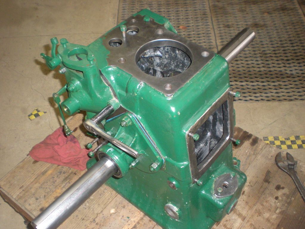
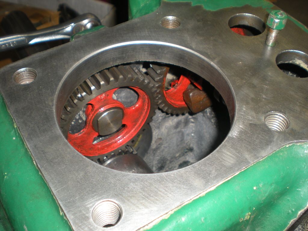
This morning i put the idler gear in and temporarly installed the cam since you got me worried about them now. at a glance i would be totally happy with that backlash. i have been into tractor transmissions that had gears this size to move the whole machine with way more backlash than this. I ran a piece of lead solder through the idler and crank gears and get bits of lead .008-.010 thick. then ran a bit of lead solder through the idler to cam gear and got .010-.018 thick. i can't imagine taking the time to build an offset bolt to close it up .006 would make the difference of a tinkers ass in hell. If those gears are junk they are junk. I did have a bit of white paint on one of the gears from when i took it out. i reached in with the wire wheel to clean it off and you could clearly see the marks from the wire wheel in the gear tooth i touched so they are super soft, usually a file will just skate off a gear tooth. so i guess i will just run it for a while and if they look like they are wearing i will make myself a whole set of gears from scratch. I have the tooling and have always wanted to make a gear. I know you can buy gear blanks to machine your self. here is the project as it sits now after a lot of cleaning.