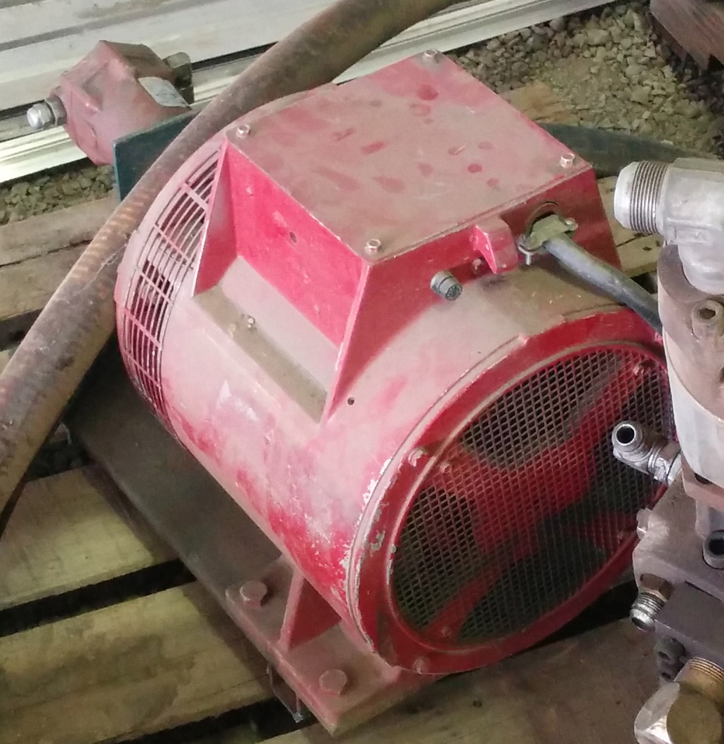
I'd purchased one of the Allmand pulleys a while back when I was working on my (then) 12/2, but now I have a 16/2 with different specs.¬ I talked to George a few months ago, and I'm sure his pulleys are the best I can get.¬ However, the pricing made me do one of those cartoon routines where my eyes bounce out of my head on springs.¬ After that price realization, I figure this gives me a good excuse to become more familiar with the CNC components of my lathe.¬ :-)
I'm drawing up my own pulley on the ole'¬ CAD platform here, and I'll try to get my hands on a ductile iron round from one of the local foundries or maybe I'll use a steel round after some experiments with wood or plastic.¬ However, before I can embark on this adventure of Learning The Hard Way, I've got some questions that perhaps can be answered by the wisdom of the crowds:
1) What are the exact dimensions of a serpentine belt groove configuration?¬ I mean the depth of the grooves, top-of-groove width, angles of groove, etc.¬ (see below)¬ I could guess, but I'd prefer real data instead of squinting-and-measuring.
2) My measurements of the Allmand pulley seem to show that the "outside" diameter of the pulley is measured at the top of the "valleys" on the grooved area.¬ Anyone disagree?
3) I've got SK bushings as 3/4" per foot of taper.¬ Right?
SK dimensions:
http://www.maskapulleys.com/propro.htm¬ (click on "QD bushings" in the menu)
My findings thus far:
The SK bushing and primary hole part were easy, even though I'm learning a bit about this CAD program as I go.¬ Measure the two holes on the existing pulley (diameter, distance apart) then create two circles with those measurements and create a skinned solid which automatically handles the tapered cone portions (excellent!¬ no math required.)¬ Delete this cone shape from the pulley cylinder.¬ Measure the head offset cut; create cylinder; delete it from the pulley cylinder.¬ Add chamfers.
Now, the ridges are a little more complex.¬ It appears (though this is just from careful measurement with inadequate tools) that the grooves are 0.10 deep, the tops of the grooves are 0.035 wide, 0.105 "valley" width at the top (distance between the ridges on the pulley.)
Measuring a belt, it seems that the "top" of the belt ridges are 0.070 wide, which would mean that when they are riding in the pulley they should be encountering a constriction between the two "walls" of the pulley groove when the valley between the walls gets to something around that width.¬ The grooves on the belt only seem to be about 0.065 deep, so that means that the grooves on the pulley are deeper than the matching ridges on the belt, which is expected - you'd want to have the constriction be the reason that the ridges don't quite mesh exactly perfectly with the pulley, otherwise you'd be losing that friction point.¬ So that means that there needs to be a taper on the pulley grooves such that at around 0.060 (depth) the width between the two walls is 0.070.
All this fussing about the groove angles and stuff might actually be a moot point if there is enough surface friction just with straight-cut grooves on the pulley.¬ But I'll try to be a perfectionist in design, if not construction. :-)
JT


